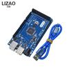
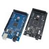
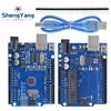
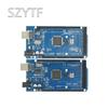
High-concerned chemical : none
Type : Module
Brand Name : DIY NOW
Origin : Mainland China
Condition : New
Product parameters:
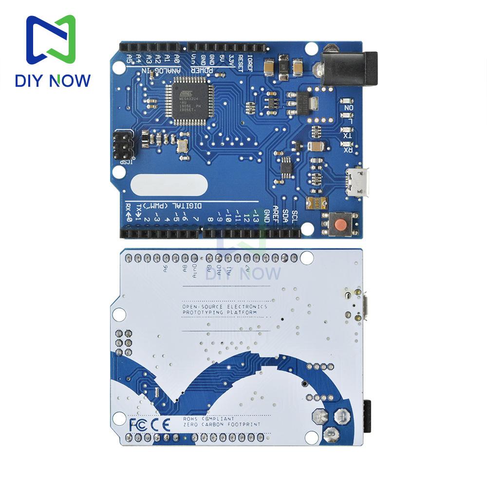
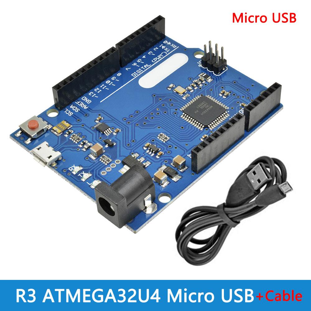
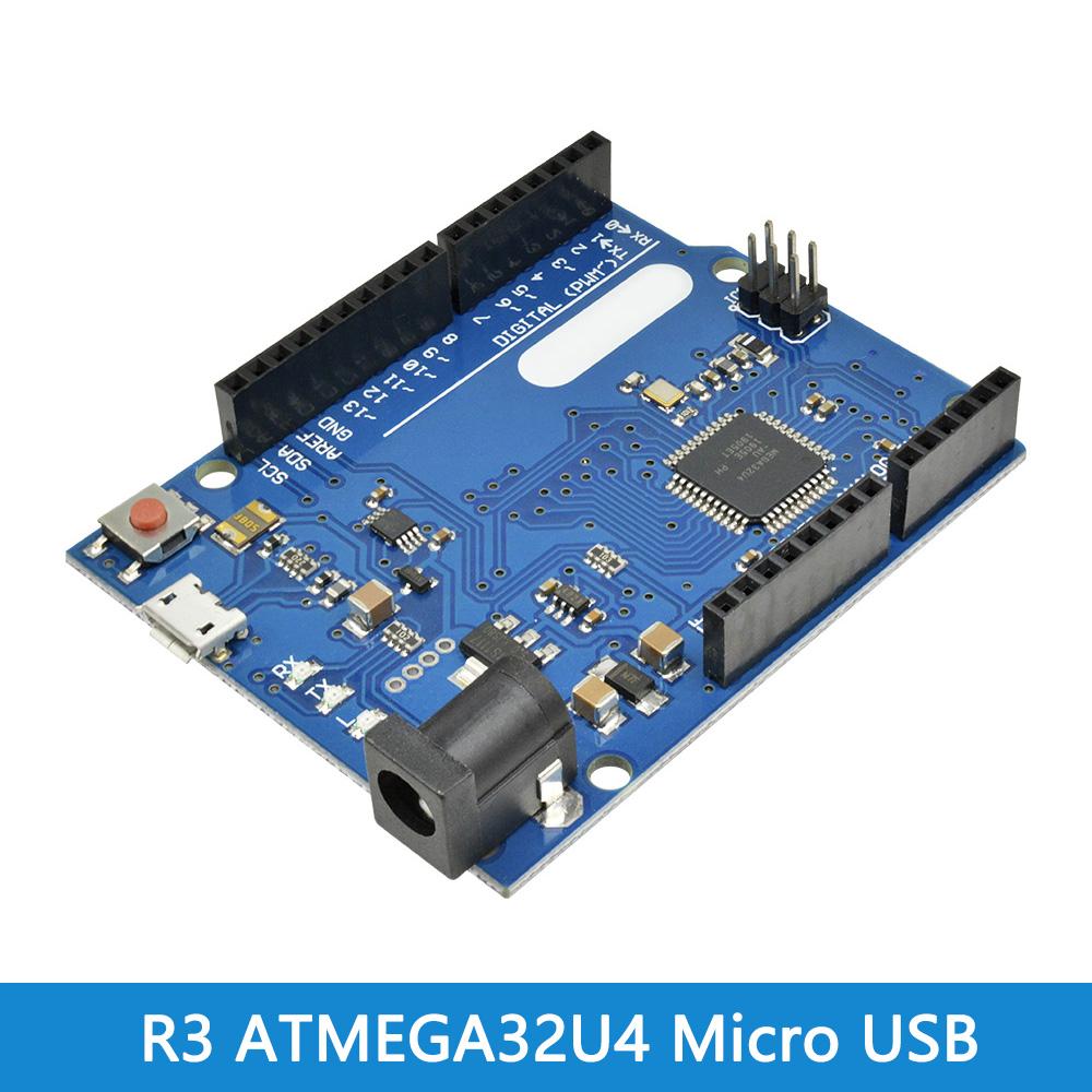
•Controller: ATmega32u4 MU
•Working frequency: 16 MHz
•Working voltage: 5V
•Input voltage (recommended): 7-12V
•Digital IO port: 20
•PWM channel: 7
•Analog input: 12
•Maximum allowable current of 5V digital/analog port: 40 mA
•Maximum allowable current of 3.3V digital/analog port: 50 mA
•Flash Memory: 32 KB (ATmega32u4) of which 4 KB used by bootloader
•SRAM: 2.5 KB (ATmega32u4)
•EEPROM: 1 KB (ATmega32u4)
Data line length is about 30CM
Shipping list:
1*module
1*data line
Product Introduction
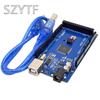
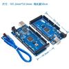
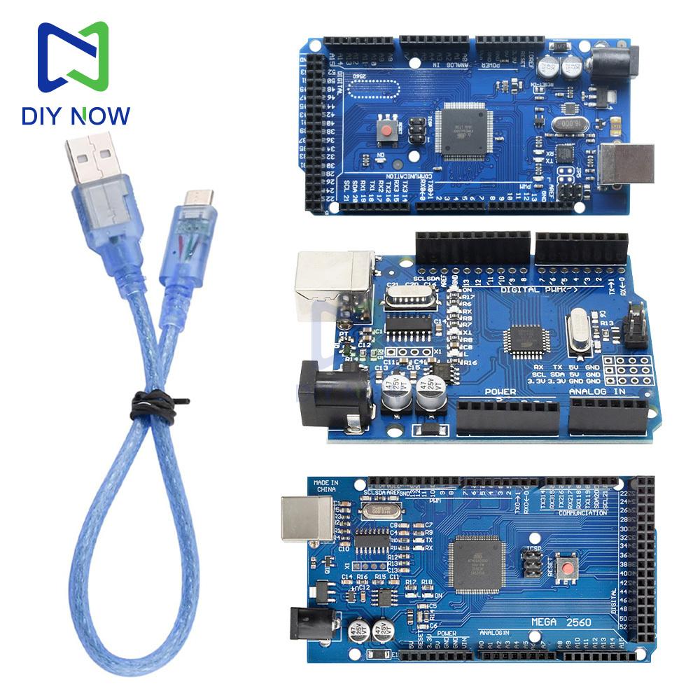
Mega has two power supply options, USB direct power supply or external power supply. The power supply selection will switch automatically. For external power supply, you can choose AC-to-DC adapter or battery. The limit voltage range of this control board is 6V~12V, but if the voltage provided is less than 6V, the I/0 port may not be able to provide 5V voltage, so it will be unstable; if the voltage provided is greater than 12V, the voltage regulator may have overheat protection, and it is more likely to damage the Arduino MEGA. Therefore, the recommended operating power supply is 6.5~12V, and the recommended power supply is 7V or 12V.
Product parameters
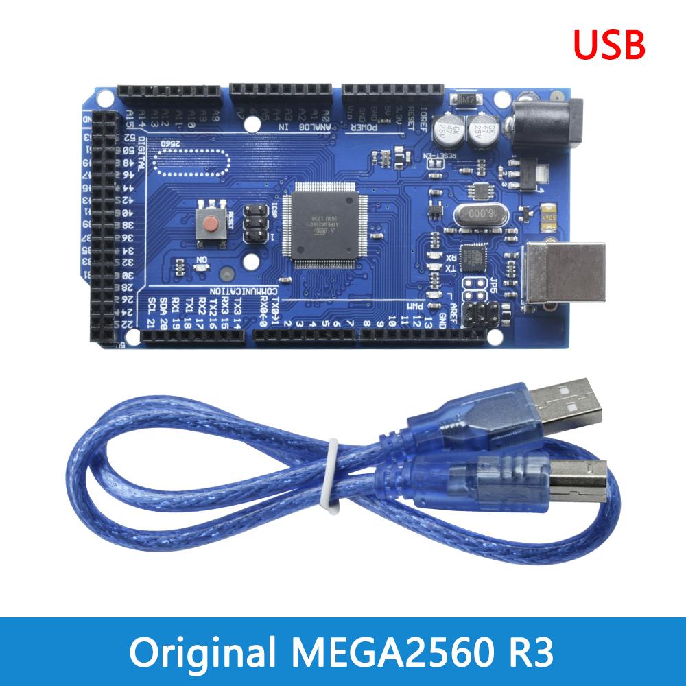
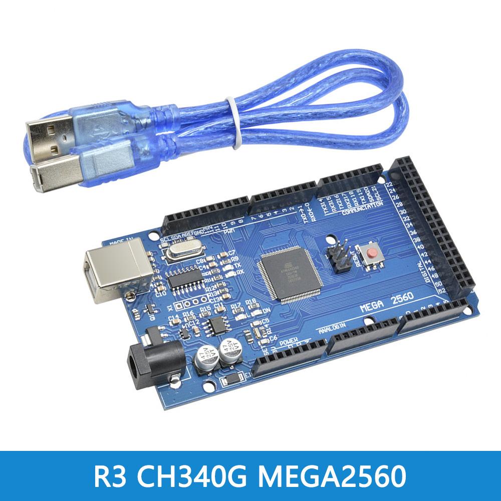
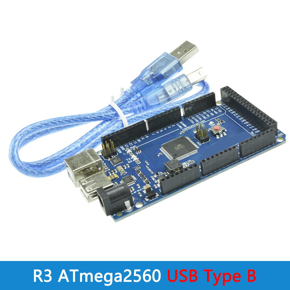
Product model: ATmega2560
Operating voltage; 5V
Input voltage; 7-12V
UT power supply; 6-20V
Digital input and output pins; 54 (15 of which provide pulse width modulation output)
Analog input pins; 16
DC current for each input/output pin; 40mA
DC current for 3.3V pin; 50mA
Memory; 256 kilobytes, of which 8 kilobytes are used by the boot loader
SRAM 5KB
Electrically erasable read-only memory; 4KB
Clock speed; 1 6MHz
Delivery list
1*module
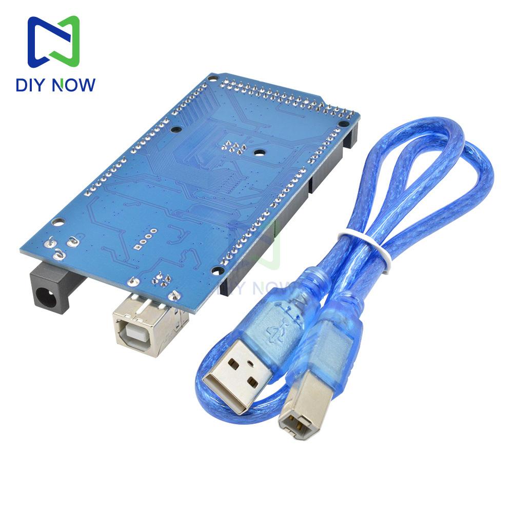
1*USB cable
Product Description:
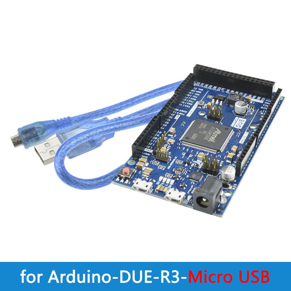
Due is a special product. Currently, there are not many known Due compatible Shields, mainly because of differences in class libraries. Due and Ar MEGA 2560 have the same pin definitions, but the power supply parameters of the I/O ports are different. There is a warning on the Ard Due official website:
Our store has conducted strict tests on each Due before delivery. Please read the relevant instructions and documents on the Due official website carefully before use. Our store is not responsible for any damage to Due caused by improper operation.
For more solutions to Due related problems, you can search the A official forum: l
The wrong USB download port was selected. Please check the download port that matches the actual connection of the USB cable to Due in the menu bar Board in the Ard 1.5.x software.
Product parameters:
Processor AT91SAM3X8EA
Operating voltage 3.3V
Input voltage 7-12V
Input voltage (limit) 6-20V
Digital I/O ports 54 (12 PWM Output)
Analog input pins 12
Analog output pins 2 (digital-to-analog conversion)
Male I/O port DC output total current 130mA
3.3V power pin can provide 800 mA current
5V power pin can provide 800 mA current
Internal flash memory capacity 512KB
SRAM96 KB (two banks: 64KB and 32KB)
Clock frequency 84 MH
Delivery list:
1*module
1*USB cable
Product Overview:
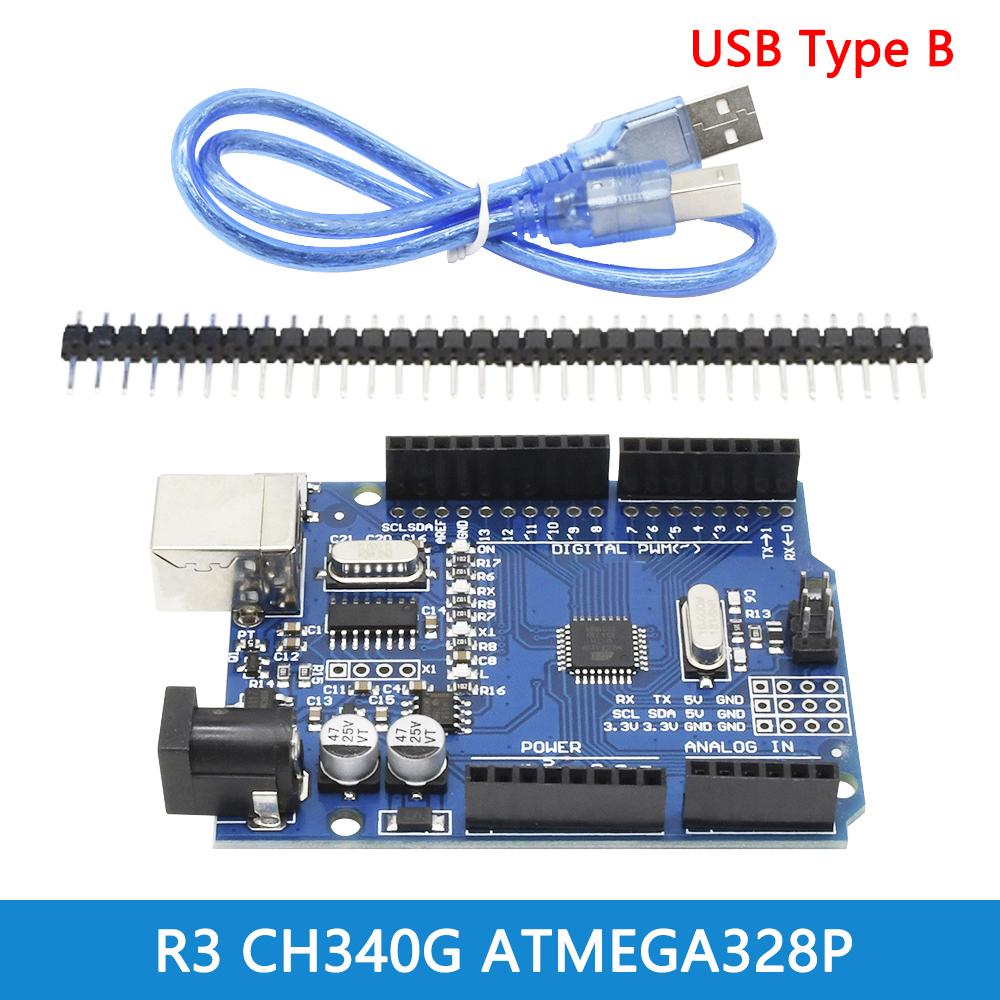
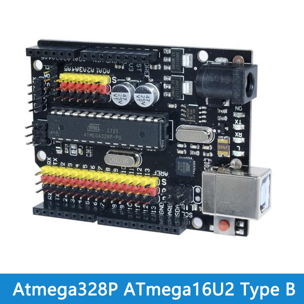
The R3 development board is a microcontroller board based on ATmega328P. It has 14 digital input/output pins (6 of which can be used as PWM outputs), 6 analog inputs, 16MHz crystal clock, USB connection, power jack, IIC, SPI interface and reset button. It only needs to be connected to the computer via a USB data cable for power supply, program download and data communication.
Parameters:
USB power supply voltage: 5V
DC port power supply voltage: 7V-12V
Main controller model: ATMEGA328P
USB to serial port chip model: CH340G
Digital 10 ports: 14 (6 of which can be used as PWM ports)
External power supply current limit 1A
I0 port current limit 40mA
Analog input pins: 6 (2 of which can be used as 12C interfaces)
Flash memory capacity: 32KB
(2KB of which has been used as BootLoader space)
SRAM: 2KB
EEPROM: 1KB
Clock frequency: 16MHZ
Pin introduction:
Power pin: The development board can provide 3.3V and 5V voltage outputs, and the Vin pin can be used to power the development board from an external power supply. Analog In pin: Analog input pin, the development board can read external analog signals, A0~A5 are analog input pins.
Digital pin: R3 has 14 digital I/0 pins, 6 of which can be used for PWM (pulse width modulation) output. Digital pins are used to read logic values (0 or 1) or as digital output pins to drive external modules. Pins marked with "~" can generate PWM.
TX and RX pins: The two pins marked with TX (transmit) and RX (receive) are used for serial communication. The LED lights marked with TX and RX are connected to the corresponding pins and will flash at different speeds during serial communication.
Pin 13: The development board marks the 13th pin, connected to the onboard LED light, and the LED light can be controlled by controlling pin 13. Generally, the onboard light will flash when the development board is powered on, which can help detect whether the development board is normal.
How to use:
Download IDE
Plug in the development board, install the driver, select the board in the IDE
Select the COM port, which can be checked in the device manager
It is best to select the built-in routine program first and burn it in
Delivery list:
Module X1
Pin header X1
Data cable X1
Product features:
1. This version is optimized on the original version, which not only ensures complete compatibility with the original version, but also facilitates everyone's use.
2. The RESET circuit has been improved to prevent accidental reset of RESET, and the circuit is more stable.
3. In addition to providing the traditional USB to serial port function, users can also program and define other functions by themselves.
4. More functions, such as configuring the USB port as a mouse, keyboard, game joystick, camera, etc.
5. Solved the incompatibility and instability of the traditional 2560 board on win7 and win8 systems.
Product parameters:
Product interface: Type-B/TYPE-C interface
Working voltage: 5v
Input voltage: 7-12V
UT voltage: 6-20V
Analog input pins: 16
DC current of each input/output pin: 40mA
Clock speed: 16MHz
How to use:
1. Download Ard's IDE
Download address: http://Ard.cc/en/Main/Software (copy and open)
2. Download USB chip driver
Download address:
http://www.wch-ic.com/download/list.asp?id=126
3. Plug in the 2560 development board, the driver will be automatically installed
4. Select the board MEGA2560 in die
5. Select the COM port, which can be checked in my computer, the port in your 2560 development board
6. First select the routine program that comes with Ard and burn it in
Advantages:
1. Completely solve the incompatibility and instability of the traditional 2560 board on win7 and win8 systems.
2. The main control chip ATMEGA2560-16 remains unchanged, and the USB chip 16u2 is replaced. The Ard project team has its own ideas for launching products using ATMEGA8U2 and ATMEGA16U2 versions. In most applications, these USB interface chips are only used as serial ports for "flashing" and communication. Using professional USB chips can not only reduce costs, but also meet the application requirements.
Wiring product list 1:
1 X R3 improved version
1X connecting cable
Description:
Mega ADK is an Arduino-based device-oriented controller with a very small size and is compatible with MEGA ADK and Google ADK. Mega ADK allows development using Google's ADK and can run on 2.3.4 or 3.1.
A large number of sensors and application modules can be connected, such as Hall sensors, button modules, thermistors, accelerometers, LDRs, potentiometers, touch sensors, joystick sensors, and MOSFET modules, etc.
Technical specifications:
Controller: ATmega2560
Operating voltage: 5V
Input voltage: 7-12V
Ultimate voltage: 6-15V
Digital ports: 54 (14 of which are PWM outputs)
Analog ports: 16
IO port output current: 40 mA
3.3V power supply output current: 100 mA
Flash: 256 KB of which 8 KB used by bootloader
SRAM: 8 KB
EEPROM: 4 KB
Crystal oscillator: 16 MHz
Delivery list:
Module X1
Data cable X1
label:yes




 Remboursement en cas de non-livraison